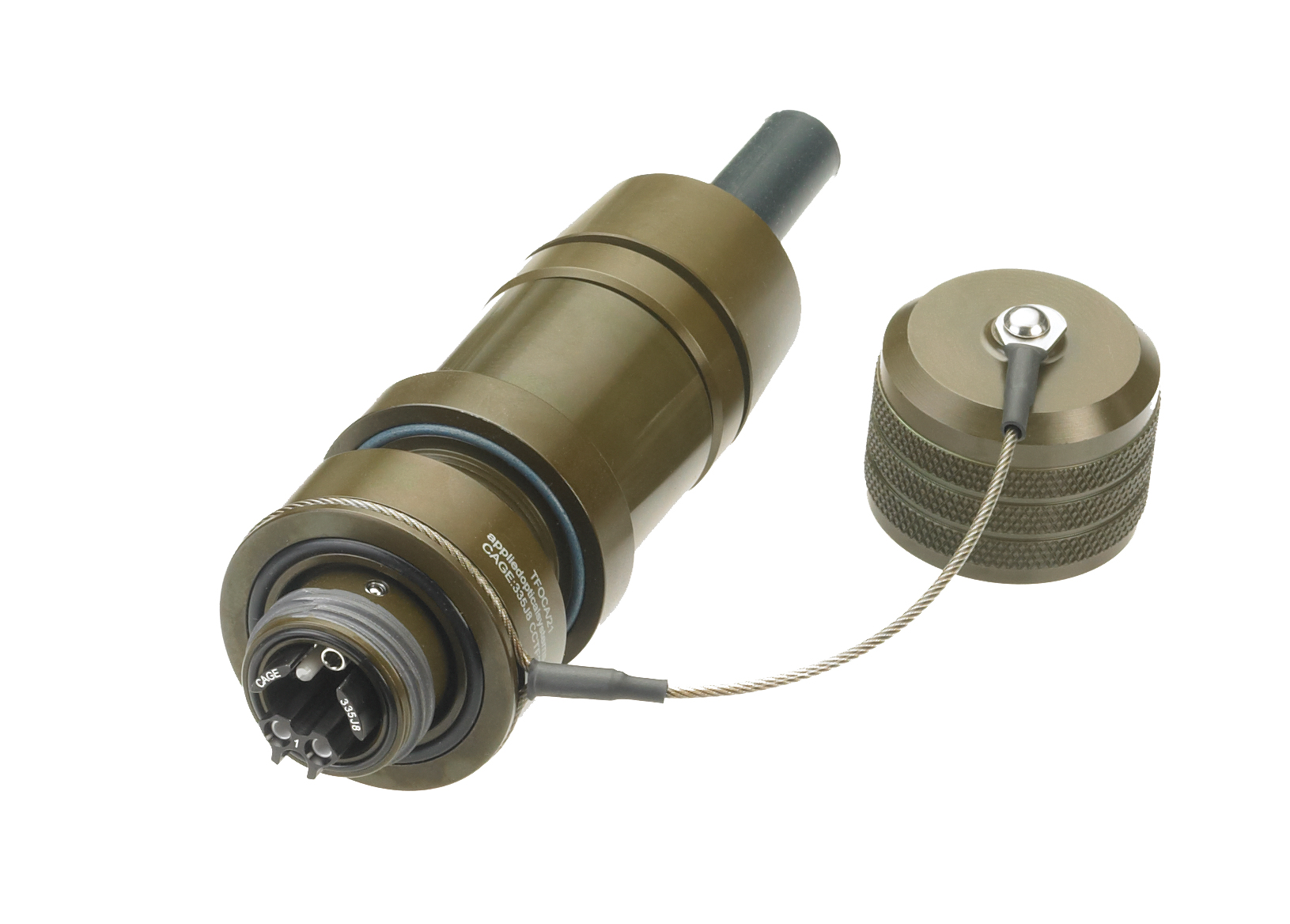
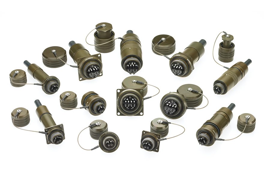
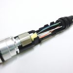
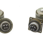
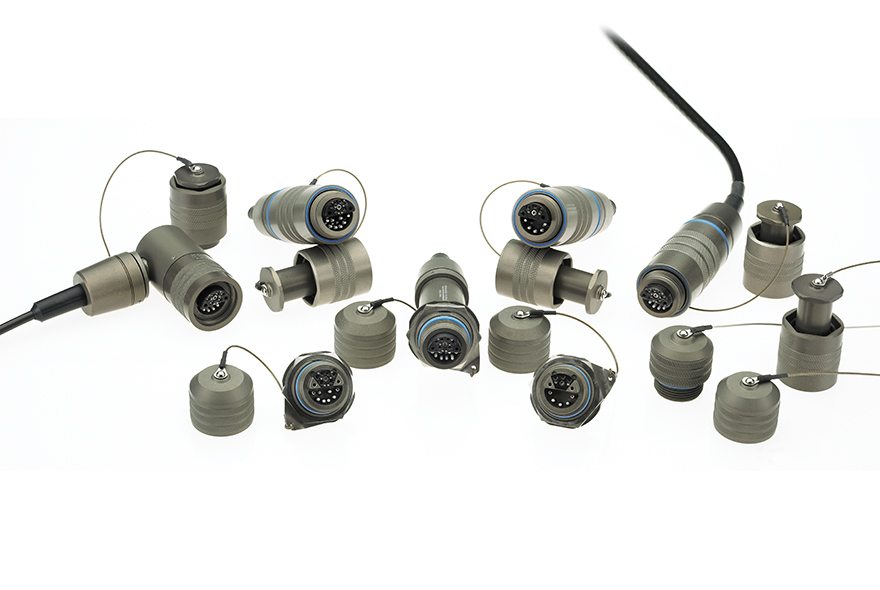
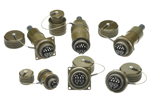
COTS M83526 4-CH Connector Family
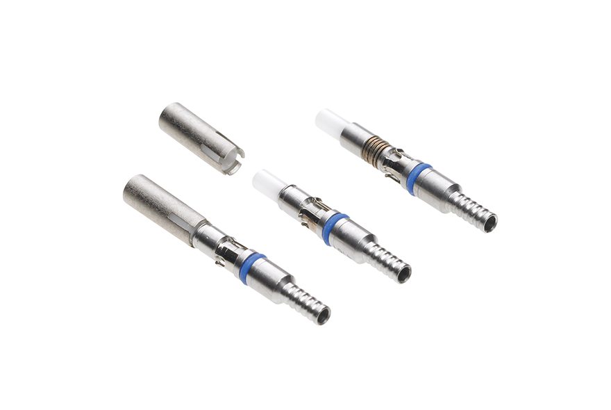
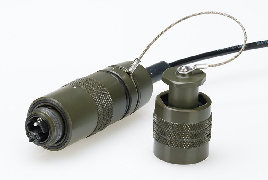
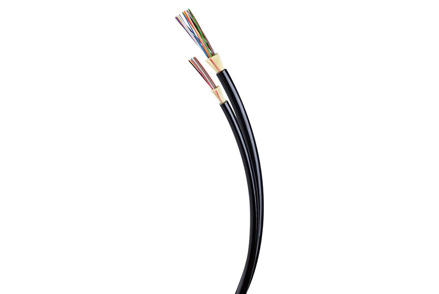
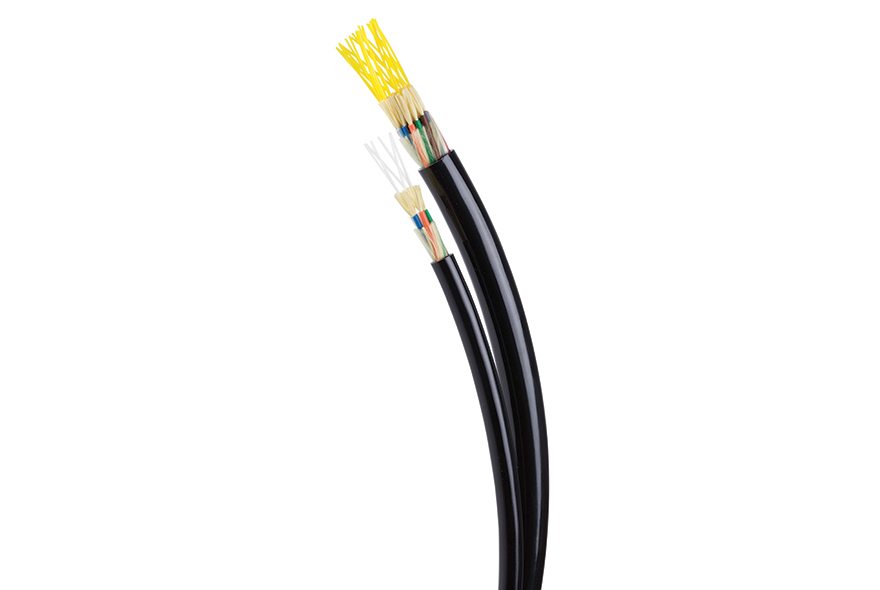
Installation zone RECOMMENDATIONOCC’s Tactical Fiber Optic Connector, COTS-83526, (TFOCAII®) is designed to the MIL-PRF-83526/16 & /17 specification and approved to the US Army CECOM A3302584 specification for Tactical Fiber Optic Connector Assemblies. Available in two shell sizes (2, 4, 6, 8 and 12 Channel options) the hermaphroditic design of this connector family allows for quick deployment and versatility in the field. The environmentally sealed terminus system offers a “free-floating” capability utilizing commercially available 02.5mm ceramic ferrules, relying on the Insert Cap of the COTS-83526 connectors to retain the ceramic alignment sleeve. This connector family provides a robust deployable network solution with superior optical performance while maintaining resistance to the prolonged abuse of the elements and harsh environments. Coupled with our 85045/8A Qualified (QPL) ground tactical cable, OCC provides the most rugged solutions the industry has to offer.
Applications
- Ground Tactical Networks – US Army, Navy, Marine Corps
- Aerospace Ground Communications
- Emergency Management or Restoration – FEMA, DHS
- Industrial: Oil & Gas, Mining, Energy and Automation
- Broadcast and Audio/Video
- Sensing and Security
Features
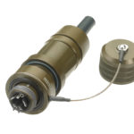
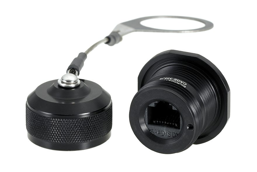
- Hermaphroditic, or genderless design allows for daisy chaining Plug-to-Plug assemblies for customized field length requirements.
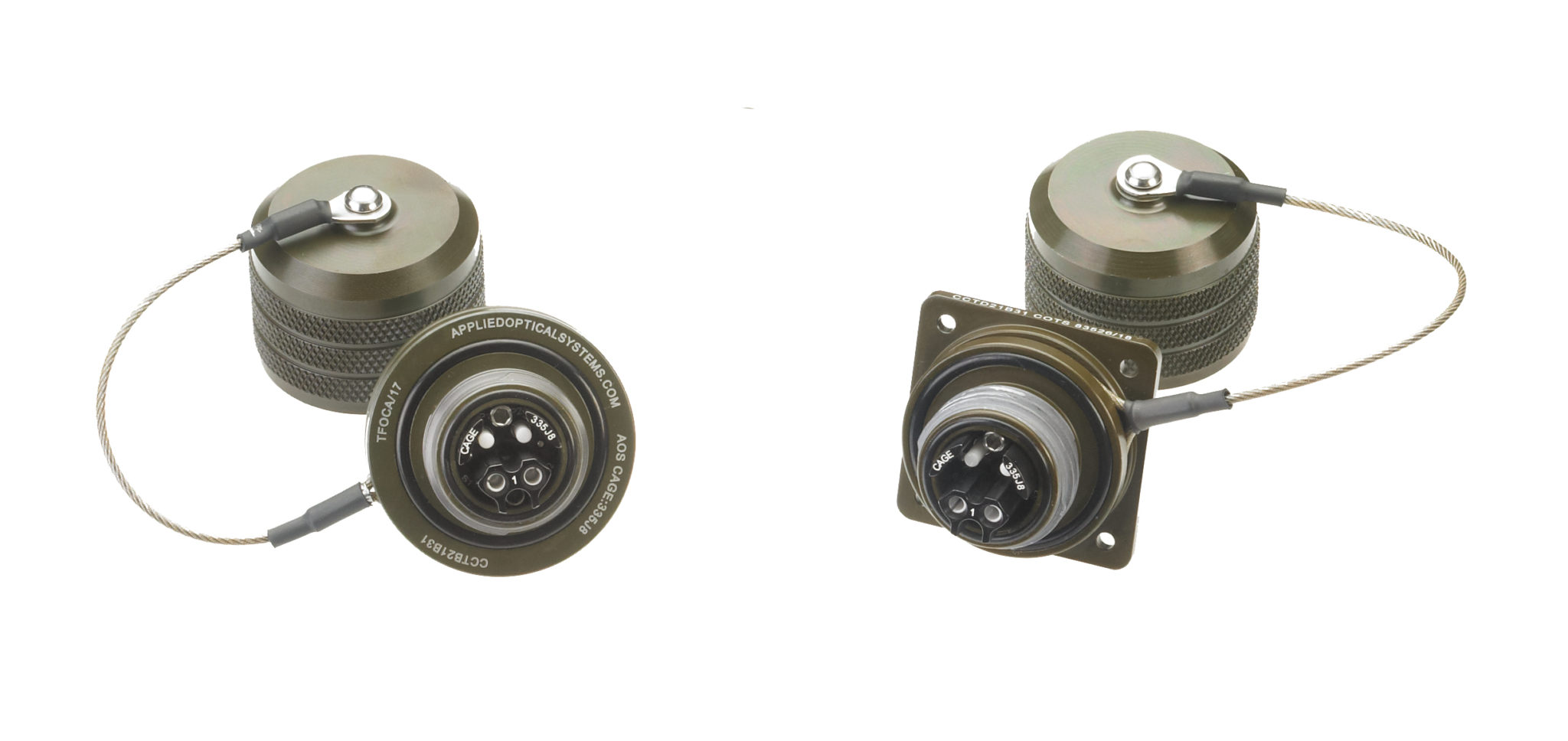
- Hermaphroditic Dust Cap mates with both Plug and receptacle dust caps to prevent dust and moisture during deployment.
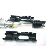
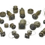
- Receptacles are customizable with Jam Nut and Flange Mount options, both internal and external mount, with or without strain relief (SRR)
- Zinc-Nickel standard plating provides superior resistance in corrosive environments.
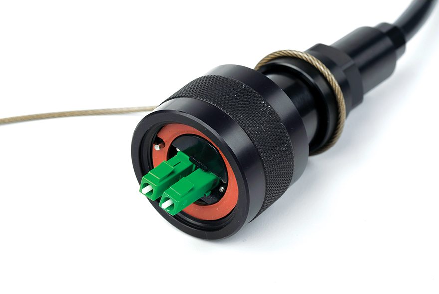
- Ceramic Split Alignment Sleeves improve Insertion Loss performance over Solid Sleeves and are retained within the Insert Cap, preventing sleeve misplacement during maintenance routines.
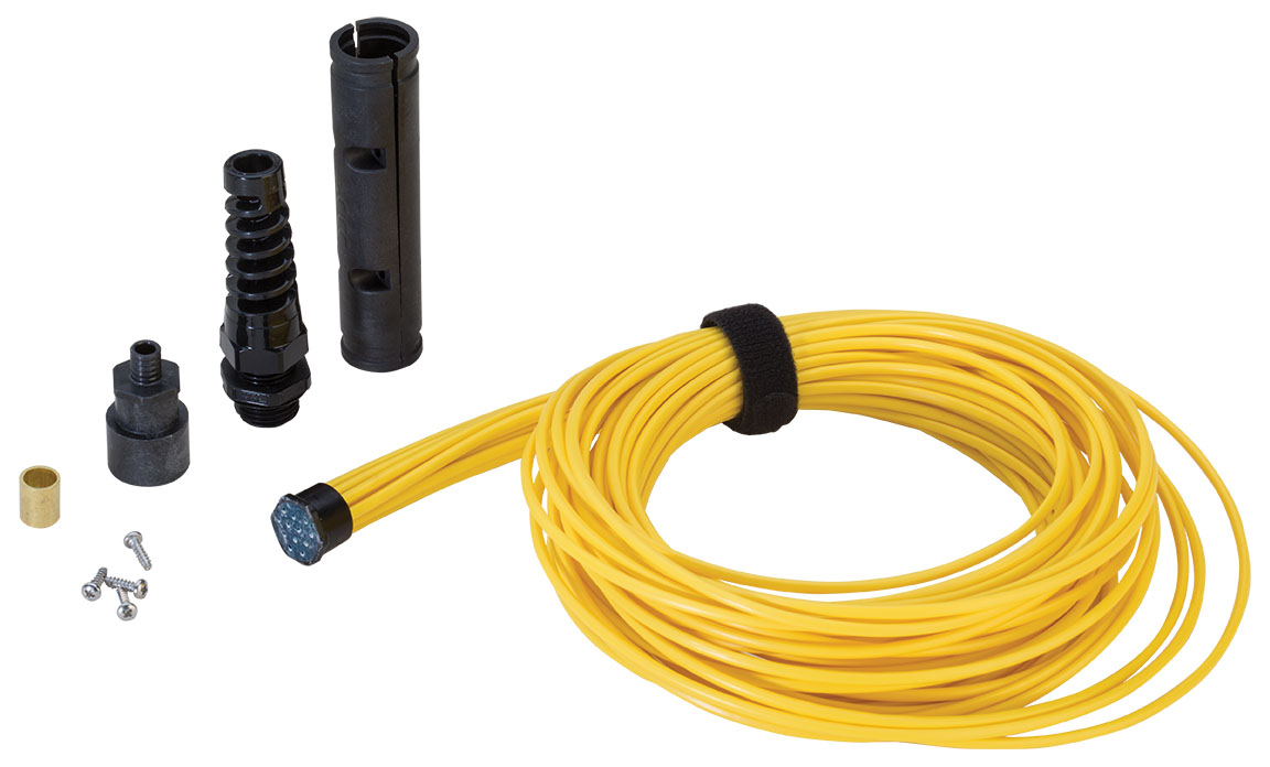
- Enhanced Kevlar Retention System supports 400 lb. pull strength without degradation of optical signal.
- Integrated "Push-Pull" system allows operators to easily terminate Plugs and Receptacles in an efficient, non-complex format.
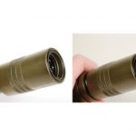
- Dry Film Lubrication coating on the mating Threads extends the life cycle of the connectors, self-lubricating through repeated mating cycles.
- Environmentally Sealed to meet IP-68 requirements.
- Fully inter-mateable with the AFSI TFOCAII® and other industry connectors meeting the MIL-PRF-83526/16, /17 interface specification.
Standards
|
PERFORMANCE SPECIFICATIONS |
||
|
PERFORMANCE |
SPECIFICATION |
PARAMETER |
|
Insertion Loss (multimode) |
EIA/TIA-455-171 |
0.50dB – Typical, 0.75dB – Maximum |
|
Insertion Loss (single-mode) |
EIA/TIA-455-171 |
0.40dB – Typical, 0.75dB – Maximum |
|
Back Reflection (single-mode, UPC polish) |
EIA/TIA-455-107 |
-50dB – Typical, -40dB – Maximum |
|
Operating Temperature |
TIA/EIA-455-5 |
-54° C to + 71° C |
|
Storage Temperature |
TIA/EIA-455-5 |
-57° C to + 85° C |
|
Mating Durability |
TIA-455-21 |
2000 cycles |
|
Impact |
TIA/EIA-455-2 |
Method B, Omit wall pipe |
|
Twist |
TIA-455-36 |
±90° rotation, one cycle/ 5sec., 1000 cycles |
|
Cable Sealing Flex |
EIA/TIA-455-1 |
Procedure I |
|
Cable Retention |
TIA-455-6 |
400 lbs min. |
|
Crush Resistance |
TIA-455-26 |
450 lbs |
|
Temperature Life |
TIA/EIA-455-4 |
250 Hr, 85 ± 2°C |
|
Thermal Shock |
TIA-455-71 |
Condition B-0 except 10 cycles, @ 85° C and -62° C |
|
Physical Shock |
EIA/TIA-455-11 |
Condition C, 5 shocks/axis |
|
Vibration |
TIA-455-1 |
Condition III & VI Condition C for 1.5 hr, Except III |
|
Humidity |
EIA/TIA-455-5 |
Type II |
|
Salt Spray1 |
EIA/TIA-455-16 |
Condition C |
|
Fluid Immersion |
EIA/TIA-455-12 |
All fluids subject to 24 hours |
|
Water Submersion |
EIA/TIA-455-98 |
Method A, Procedure 1, 1m for 24 hours. Bulkhead mounted in watertight cube |
|
Flammability |
EIA-364-8 |
|
|
Mud Test2 |
M83526, paragraph 4.8 |
5 min. immersion, 10 cycles |
|
Electromagnetic Effects1,3 |
IEEE-299 |
20kHz, 150kHz, 14MHz, 400MHz, 600MHz, 1GHz, 2GHz, 8GHz, 10GHz, VERT. & HORZ., |
NOTES
1 Applies to ZiNi plating only
2 Sand/Topsoil substituted for Potter's Clay
3 12 CH Receptacle requires application of SRR configurations
Specifications
| Part Number | Description | Type | |
|---|---|---|---|
| CCTA10B31CA | 2-4 CH Hermaphroditic Fiber Optic Plug and Dust Cap, Cable Diameter: 0.190"-0.239" | Plug | |
| CCTA10B31CB | 2-4 CH Hermaphroditic Fiber Optic Plug and Dust Cap, Cable Diameter: 0.240"-0.269" | Plug | |
| CCTB21B31C | 2-4 CH Jam Nut Fiber Optic Receptacle and Female Dust Cap, EMI | Receptacle | |
| CCTD21B31C | 2-4 CH Flange Mount Receptacle Fiber Optic Receptacle Female Dust Cap, EMI | Receptacle | |
| CCTC21B31C | 2-4 CH External Jam-Nut Receptacle Fiber Optic Receptacle and Female Dust Cap, EMI | Receptacle | |
| CCTE21B31CA | 2-4 CH Jam Nut Strain Relief Receptacle and Female Dust Cap, EMI, Cable Diameter: 0.190"-0.239" | Strain Relief Receptacle | |
| CCTE21B31CB | 2-4 CH Jam Nut Strain Relief Receptacle and Female Dust Cap, EMI, Cable Diameter: 0.240"-0.269" | Strain Relief Receptacle | |
| CCTG21B31CA | 2-4 CH Flange Mount Strain Relief Receptacle(SRR) and Female Dust Cap, EMI, Cable Diameter: 0.190"-0.239" | Strain Relief Receptacle | |
| CCTG21B31CB | 2-4 CH Flange Mount Strain Relief Receptacle(SRR) and Female Dust Cap, EMI, Cable Diameter: 0.240"-0.269" | Strain Relief Receptacle | |
| CCTF21B31CA | 2-4 CH External Jam Nut Strain Relief Receptacle(SRR) and Female Dust Cap, EMI, Cable Diameter: 0.190"-0.239" | Strain Relief Receptacle | |
| CCTF21B31CB | 2-4 CH External Jam Nut Strain Relief Receptacle(SRR) and Female Dust Cap, EMI, Cable Diameter: 0.240"-0.269" | Strain Relief Receptacle | |
| TC1640DA | 2.5mm, Environmental Resisting, Fiber Optic Termini, 126µm I.D. | Termini | |
| TC1739AA | Dummy Termini for 4 CH and 12 CH for COTS-83526 | Termini | |
| PC83522/16-20-S | Crimp Sleeve, Used with 3.00mm Loose-Tube Jacket | Crimp Sleeve | |
| PA35395-99-017 | Crimp Sleeve, Used with 2.00mm Loose-Tube Jacket | Crimp Sleeve |
Provisioning guidelines
1) Select the number of Dummy Termini necessary to fill a connector. Example, when planning for an 8 CH application, select 4 dummy termini to complete a 12 CH size connector
2) Crimp sleeves are recommended for use on receptacle configurations without Strain Relief (SRR). Crimp sleeves are generally used with simple loose tube cable for receptacle pigtails. 4 CH and 12 CH receptacles can also accommodate 3.00mm loose cable.
EMI/ Non-EMI Options
EMI-conductive O-rings and/or gaskets are typically provisioned with all COTS 83526-style receptacles but add additional cost to each component. Non-EMI options are available by simply ordering a receptacle part number with a “2” in the 6th digit position:
(ex: CCTG22B31CD) of part number inclusive of CCTB, CCTC, CCTD, CCTE, CCTF and CCTG configurations.
Plating Options
Most COTS M83526 component configurations are supplied with Zinc Nickel Plating with Olive Drab coloring. For the additional plating options, the “k” in the 8th digit position of the part number (ex: CCTG22Fk1CD) is selected for the plating/material of choice.
“1” Black Anodized, Mil-A-8625 TYPE 2 CLASS 2
“3” Zinc Nickel Plating, SAE AMS 2417G
“4” 303 Stainless Steel, Passivation per QQ-P-35/ASTMA967
“5” 316 Stainless Steel, Passivation per QQ-P-35/ASTMA967
“6” Naval Brass, C 46400 H02 Half Hard ASTMB 21/B21M
Instruction Sheets
Related Documents
More Harsh Environment Connectors

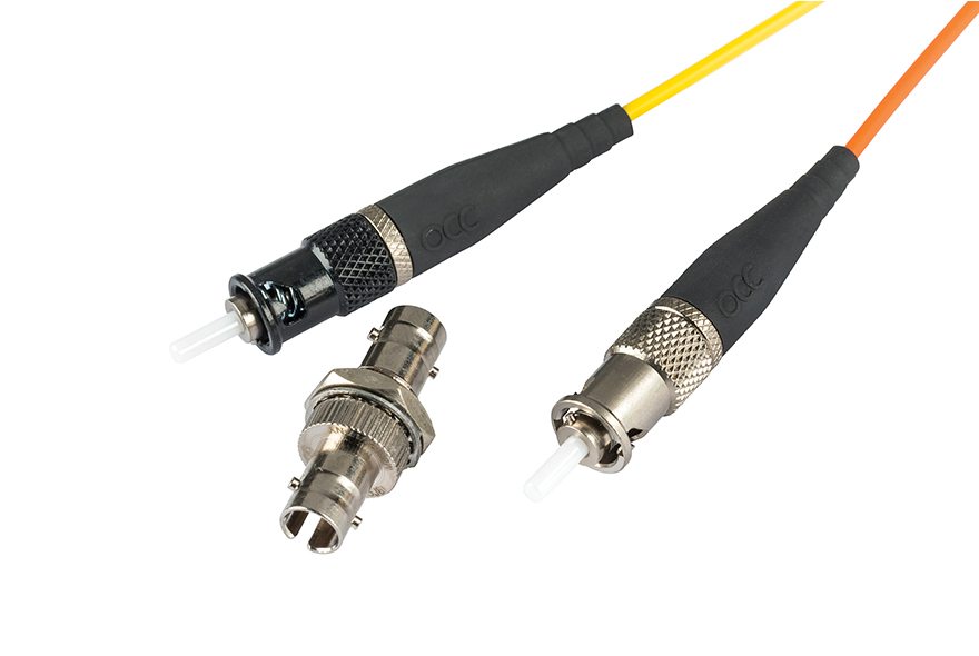
Related Products

Connections you can count on.